
Products
PLC Setting
SIEMENS SIMATIC PLC Settings
This page explains how to connect SIEMENS SIMATIC Series PLCs with DeviceXPlorer OPC Server.
For a walkthrough of the connection settings for an S7-1200/S7-1500 Series PLC, check out this video on our YouTube channel:
S7-1500 Ethernet Settings
This section explains how to configure the S7-1500 Ethernet communication settings using “STEP7 (Totally Integrated Automation Portal V12)”.
To communicate with the S7-1500 by TCP/IP Ethernet, CPU and Ethernet settings will need to be configured properly. Please follow the directions below to configure the unit.
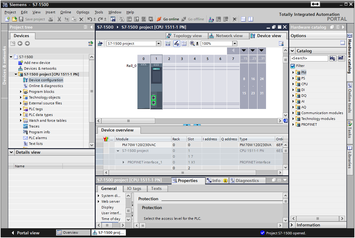
1. In STEP7 (Totally Integrated Automation Portal V12), launch S7-1500 project.
2. If this is a new S7-1500 project, add the necessary units to the Rack in Device configuration and set up the unit.
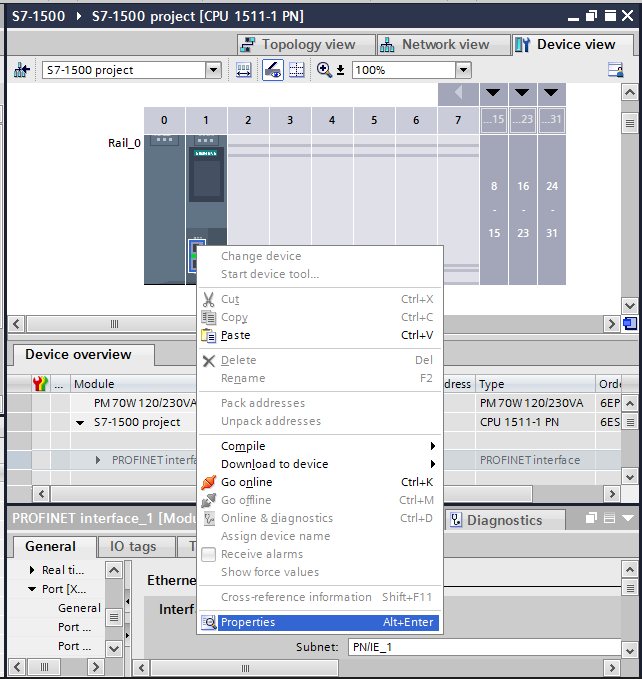
3. Right-click on the Ethernet LAN adapter in the rack and then select Properties.
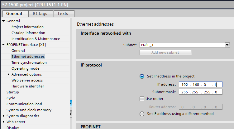
4. Specify the IP Address and Subnet mask.
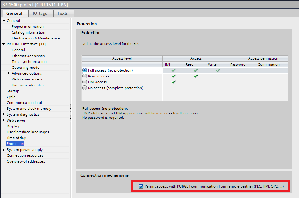
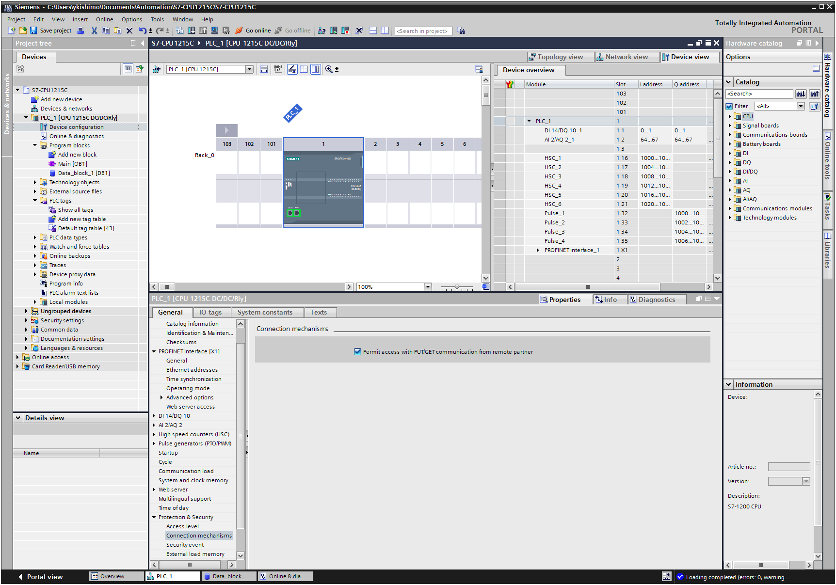
5. Under Protection, select Full access and check the “Permit access with PUT/GET communication from remote partner (PLC, HMI, OPC, …)” box for Connection mechanisms. If this box is not checked, you cannot access the CPU register from DeviceXPlorer.
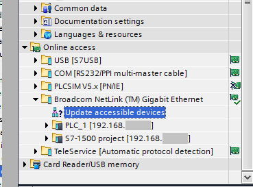
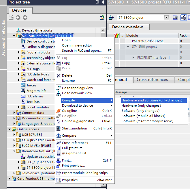
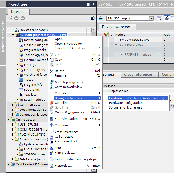
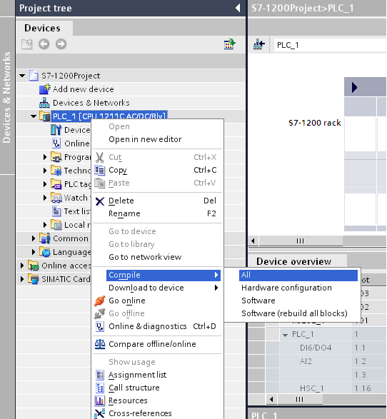
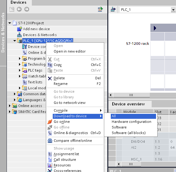
6. After completing the settings, compile all settings and download to device. A connection with the PLC by Online access is necessary for downloading to the device. If you don’t download to the CPU device, the settings will not be reflected.
7. The Ethernet settings are finished.
S7-1200 Ethernet Settings
This section explains how to configure the S7-1200 Ethernet communication settings using “STEP7 Basic (Totally Integrated Automation Portal V10)”.
To communicate with the S7-1200 by TCP/IP Ethernet, CPU and Ethernet settings will need to be configured properly. Please follow the directions below to configure the unit.
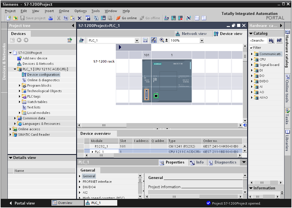
1. In STEP7 Basic (Totally Integrated Automation Portal V10), launch S7-1200 project.
2. If this is a new S7-1200 project, add the necessary units to the Rack in Device configuration and set up the unit.
- Important
In firmware version 4 or later of S7-1200, please check the “Permit access with PUT/GET communication from remote partner” box under Connection mechanisms. If this box is not checked, you cannot access the CPU register from DeviceXPlorer.
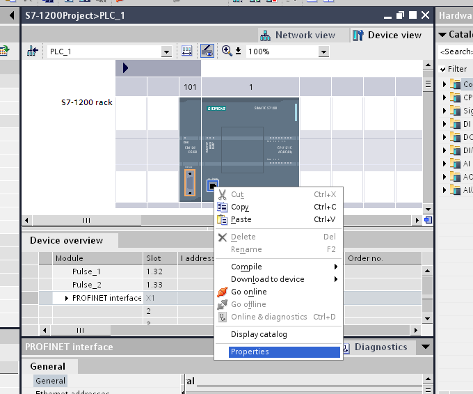
3. Right-click on the Ethernet LAN adapter in the rack and then select Properties.
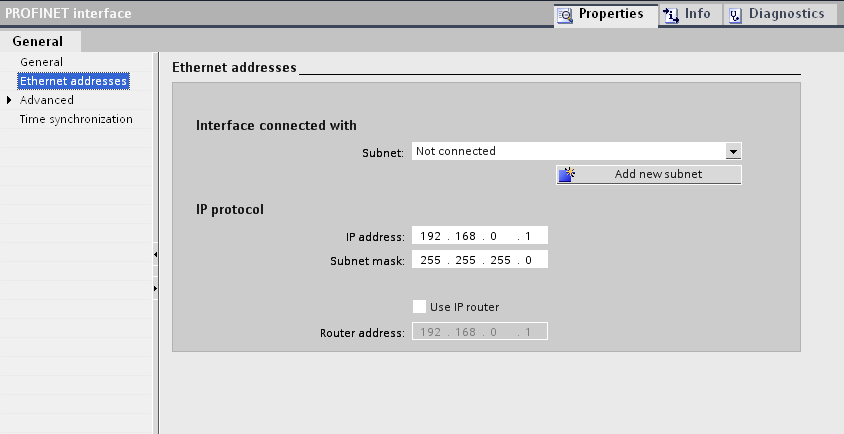
4. Specify the IP Address and Subnet mask.
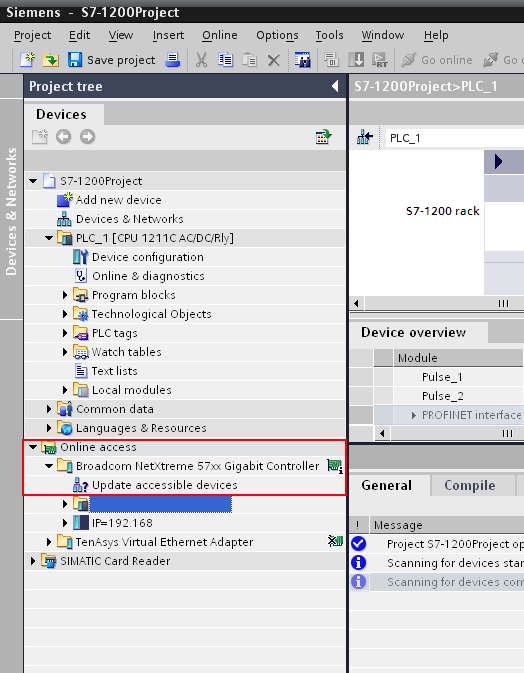
5. After completing the settings, compile all settings and download to device. A connection with the PLC by Online access is necessary for downloading to the device. If you don’t download to the CPU device, the settings will not be reflected.
6. The Ethernet settings are finished.
- Note
In S7-1200, the maximum number of PC connections for the CPU is 3 connections including SIMATIC HMI. The PC connection is the access by device of DeviceXPlorer which is set by the Resource No. of Remote TSAP "03” in device settings. At the maximum, you can access the same PLC with 3 devices of DeviceXPlorer. So please be careful about the device count of DeviceXPlorer. If you use SIMATIC HMI which is connecting with the PLC, please set within 3 connections including the SIMATIC HMI connection.
S7-300 / S7-400 Ethernet Settings
This section explains how to configure the Ethernet unit (CPU unit) communication settings using “SIMATIC Manager”. To communicate with the S7-300 / S7-400 CPU by TCP/IP Ethernet, CPU and Ethernet settings will need to be configured properly. Please follow the directions below to configure the unit.
1. In SIMATIC Manager, launch HW Configuration from the SIMATIC Station.
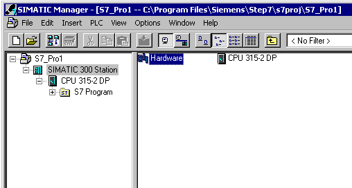
2. If this is a new SIMATIC project, add the necessary units to the Rack in HW Configuration. For the Siemens TCP/IP Ethernet communication with the CPU, at least 1 Ethernet unit capable of S7 Communications is necessary. (This includes built-in Ethernet CPU.)
3. Right-click on the Ethernet unit in the rack and then select Object Properties.
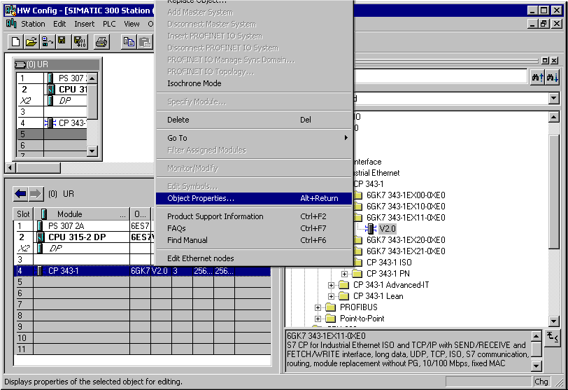
4. The dialog box should appear as shown below.
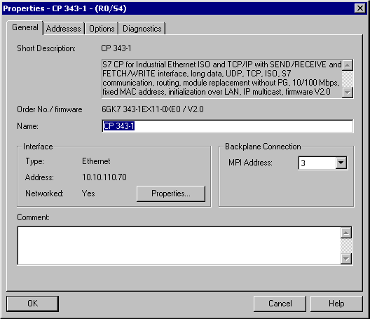
5. From the General tab, click the Properties button and the dialog appear as shown below.
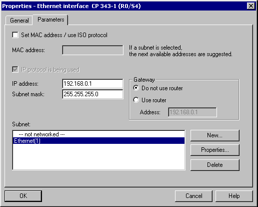
6. Specify the IP Address and Subnet mask.
7. To add a network to this unit, click “New” from Subnet menu and create the network subnet.
8. Return the HW Configuration main window.
9. Right-click on the CPU unit in the rack and select Object Properties.
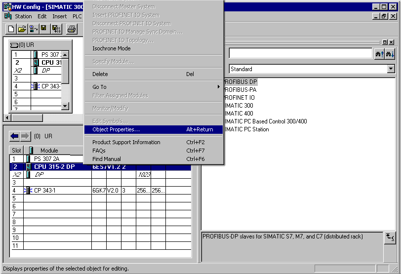
10. Select the Communication tab from the dialog box shown below.
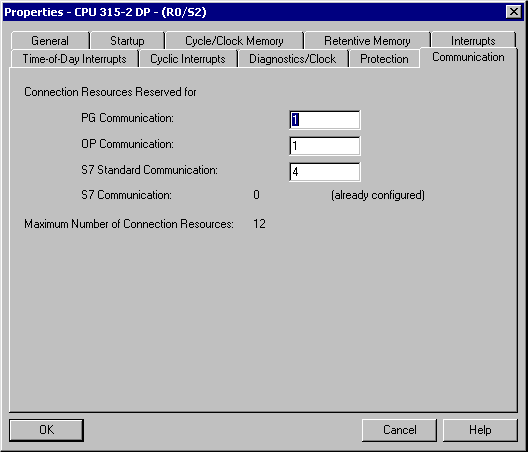
11. Configure the desired number of PG/OP and PC (S7 Communication) connections.
|
Type |
Description |
|
PG Communication |
Used for program loading, diagnostics |
|
OP Communication |
Used for operator control and monitoring |
|
S7 Standard Communication |
Communication connections not configured, MPI communications with PUT/GET |
|
S7 Communication (PC) |
Configured connections, data communications |
- Note
In S7-300 and S7-400 series, the maximum number of PC connections for the CPU equals the Maximum Number of Connection Resources minus the S7 Standard Communication, OP Communication, and PG Communication resources. Note that the Maximum Number of Connection Resources is based on the CPU, version, and firmware. In the example shown above, there are six S7 Communication (PC) connections available (12-4-1-1=6). Likewise, the number of PG and OP connections can be increased using the same concept. The PC connection is the access by device of DeviceXPlorer, which is set to the Resource No. of Remote TSAP "03” in device settings. This maximum number of PC connections is equal with the maximum accessible device count of DeviceXPlorer which connect to the same Ethernet port. (Please specify the Device settings by Resource No“03" of Remote TSAP.) Depending on the system, please balance with the number of these resources.
12. After the connections have been configured, click OK. Next, in the main HW Config window click Station > Save and Compile.
13. Click PLC > Download to confirm the changes.
S7-200 Ethernet Settings
This section explains how to configure the Ethernet unit communication settings using “STEP7 – Micro/WIN”. To communicate with the S7-200 CPU by TCP/IP Ethernet, CPU and Ethernet settings will need to be configured properly. Please follow these steps.
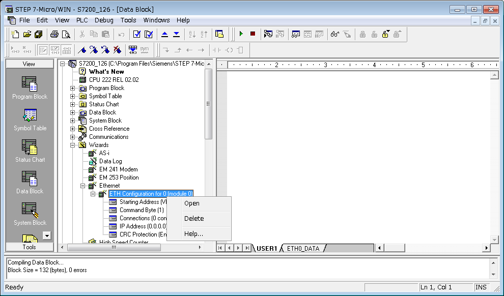
1. Launch STEP7 – Micro/WIN.
2. Right-click the Ethernet unit in Wizard, and open the property wizard.
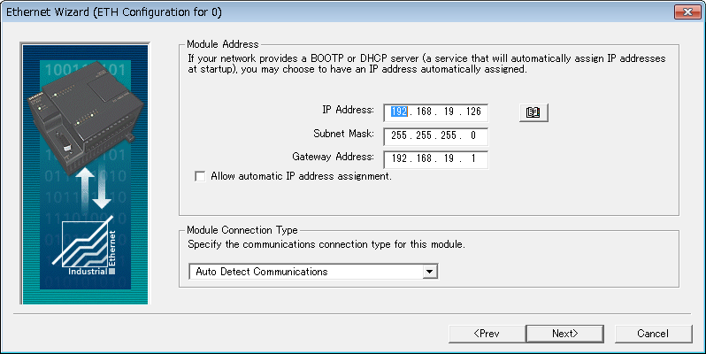
3. Progress through the wizard by clicking the Next button, until the following dialog box is displayed. Specify IP Address and Subnet Mask.
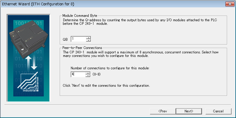
4. Specify number of connections from Number of connections to configure for this module. This number means the number of communicatable modules (includes OPC Server) with the Ethernet unit.
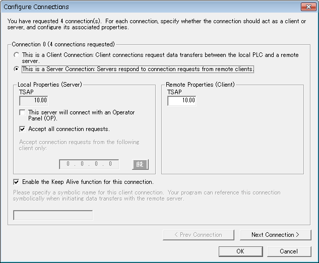
5. Configure the LocalTSAP and RemoteTSAP for each connection.
Try Today
Download a free trial version of DeviceXPlorer OPC Server to manage the data from your Rockwell AB series PLC.
- MITSUBISHI MELSEC
- OMRON SYSMAC
- JTEKT TOYOPUC
- YOKOGAWA FA-M3
- HITACHI HIDIC
- SHARP SATELLITE
- FUJI MICREX
- PANASONIC FP
- YASKAWA MP
- KEYENCE KV
- TOSHIBA PLC
- AZBIL CPL
- IAI CONTROLLER
- ROCKWELL AB
- SIEMENS SIMATIC
- CODESYS PLC
- GE PLC
- Saia PLC
- LSIS XGT
- MODBUS
- FANUC CNC
- MITSUBISHI CNC
- MITSUBISHI EDM
- KAWASAKI ROBOT
- YASKAWA ROBOT
- SEIKO EPSON ROBOT
- YAMAHA ROBOT
- SHIBAURA MACHINE
- Sumitomo Heavy Industries - Molding Machine
- The Japan Steel Works - Molding Machine
- DPRNT
- MTConnect
- BACnet
- EtherNet/IP
- MITSUBISHI RFID
- OMRON RFID
- JCC AE sensor
- COGNEX BCR
- KEYENCE BCR
- MARS TOHKEN BCR
- MITSUBISHI ECO
- IEC61850 MMS Client
- IEC60870-5-104
- DNP3
- OPC DA CLIENT
- OPC UA CLIENT
- OPC UA SUBSCRIBER
- ODBC CLIENT
- DDE CLIENT
- DxpLink CLIENT
- Modbus/TCP Server
- User Protocols
- SHARED MEMORY