
Solutions
- TOP
- Solutions
- Partner Solutions
- Patlite AirGRID
- Connection Procedure between Patlite AirGRID and DeviceXPlorer OPC Server / DeviceGateway
Connection Procedure between Patlite AirGRID and DeviceXPlorer OPC Server / DeviceGateway
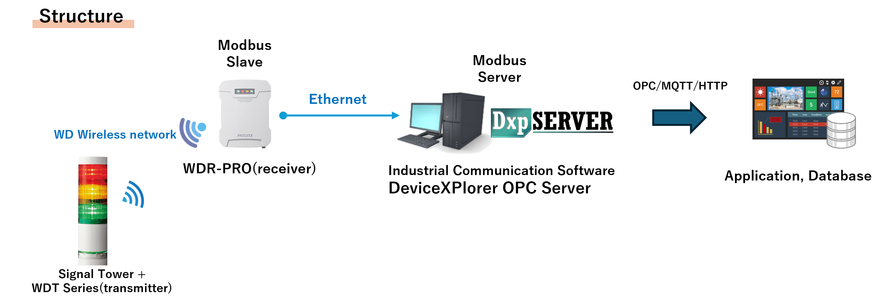
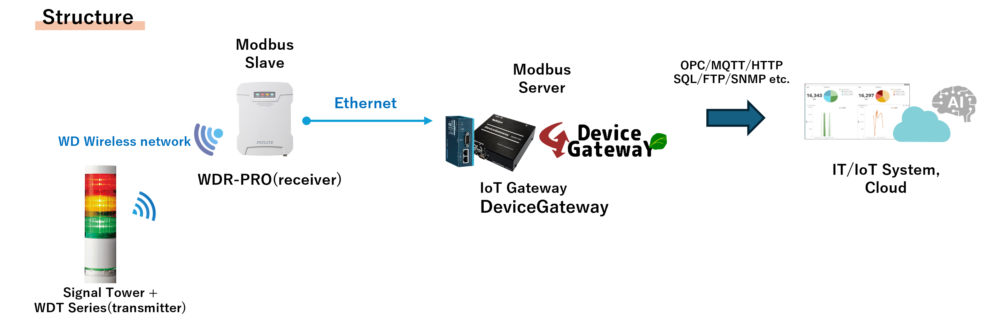
In this article, we explain the connection procedure between Patlite AirGRID and Takebishi’s DeviceXPlorer OPC Server and DeviceGateway.
Table of Contents
Connecting AirGRID with DeviceXPlorer OPC Server
1. AirGRID Settings
Before starting, make sure to complete the required setup to receive data from the Patlite signal tower and the WDT (transmitter) through the WDR-PRO (receiver).
WDR-PRO(receiver) Settings
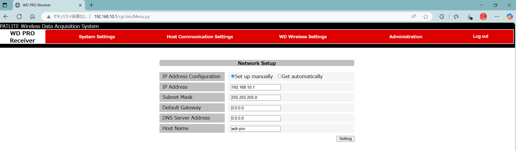
From the WDR-PRO web configuration screen, configure the network settings and Modbus/TCP settings. If necessary, also set the transmitter user name.
(1) Network Settings
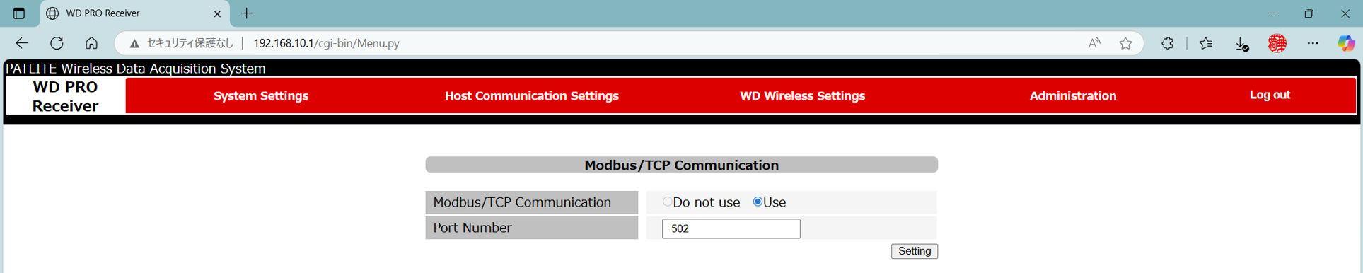
(2) Modbus/TCP Settings
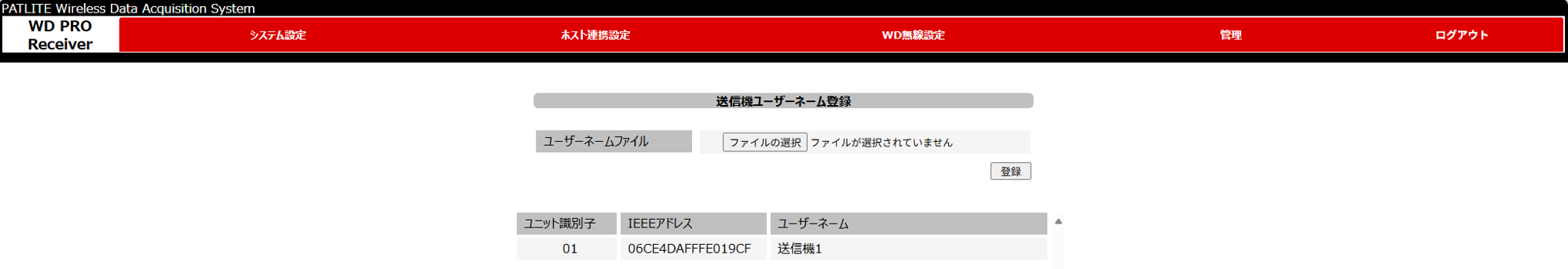
(3) (If necessary) Transmitter User Name Settings
WDT (transmitter) Settings
Use the WD Series system operation software ‘WDS-WIN01’ to check the communication between the WDT (transmitter) and the WDR-PRO (receiver). If the MAC address appears in the WDT list of ‘WDS-WIN01’, the WDR-PRO (receiver) is successfully receiving the signal tower information.
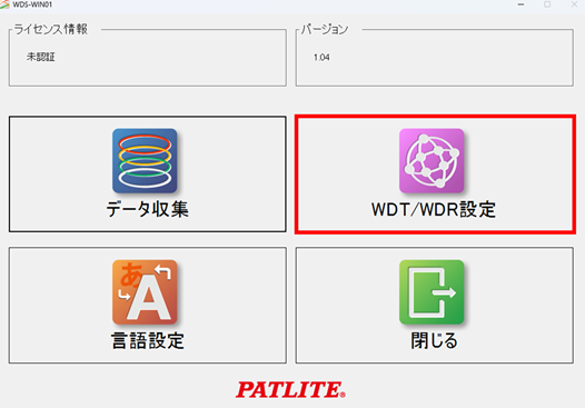
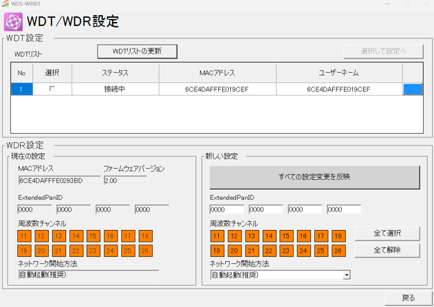
(1) In the ‘WDS-WIN01’ screen, select [WDT/WDR settings].
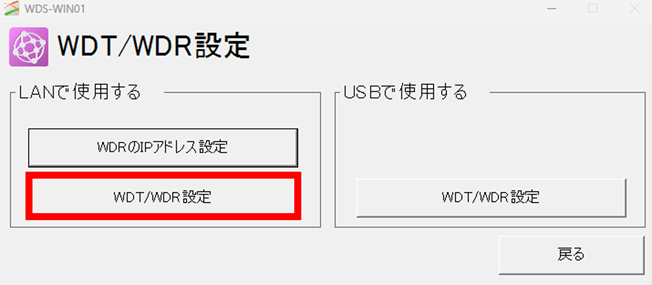
(2) Select [WDT/WDR settings].
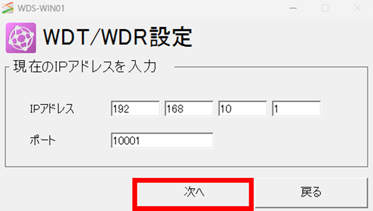
(3) Enter the IP address of the WDR-PRO and click [Next]
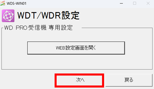
(4) [Next]
(5) The information of the target WDT will be displayed in the WDT list.
2. DeviceXPlorer OPC Server Settings
Configure the settings required to connect to AirGRID using Modbus Ethernet communication in DeviceXPlorer OPC Server.
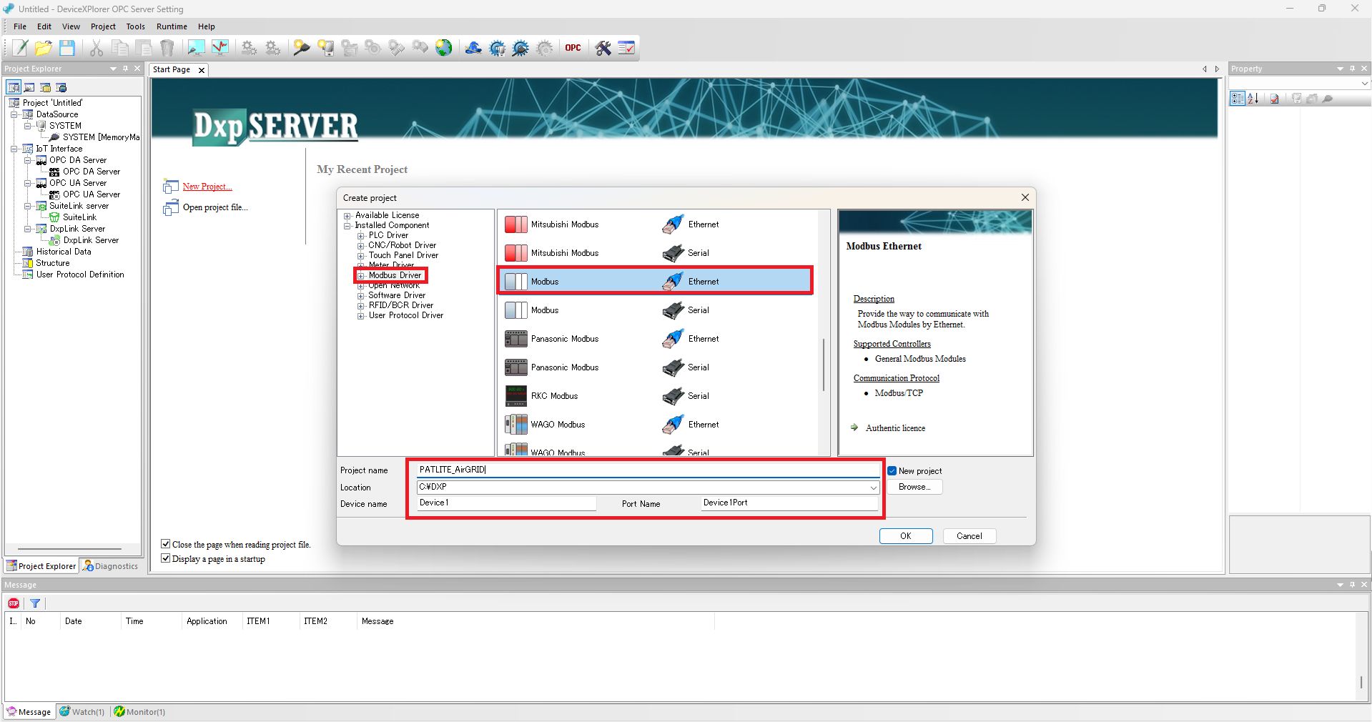
(1) From the Project Creation screen, select [Modbus Driver] in the tree on the left, choose [Modbus – Ethernet], and then click [OK].”
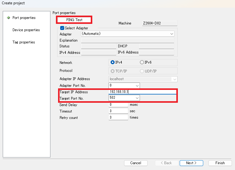
(2) Configure the port settings. Enter the IP address assigned to the WDR-PRO in ‘Target IP Address’, and enter ‘502’ (default) in ‘Target Port Number’. You can run a ping test from this screen. After confirming that the ping response is successful, click [Close] and then [Next].
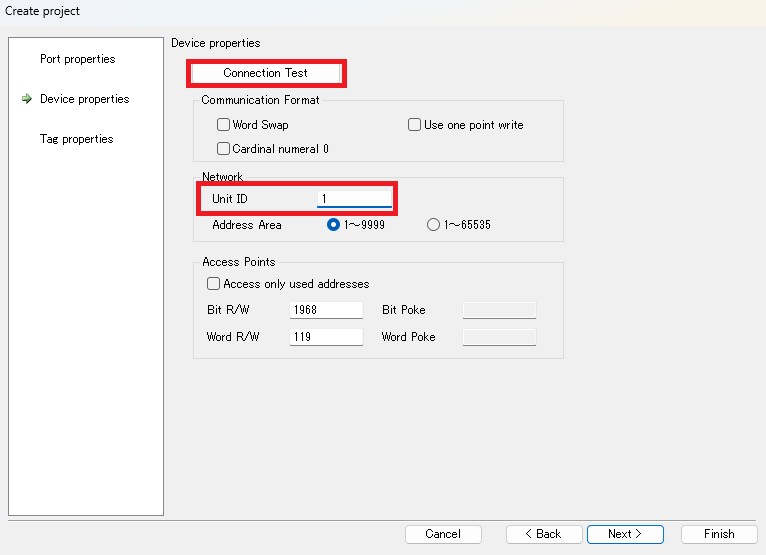
(3) Configure the device settings. Enter ‘1’ in ‘Unit ID’. You can also run a connection test from this screen. After confirming that ‘Connection Test Success’ is displayed, click [Close] and then [OK].
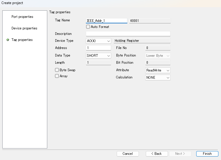
(4) Finally, configure the tag settings.AirGRID assigns WDT data to holding registers (addresses starting with ‘4’). For the list of data mappings, refer to the application note for the WDT.
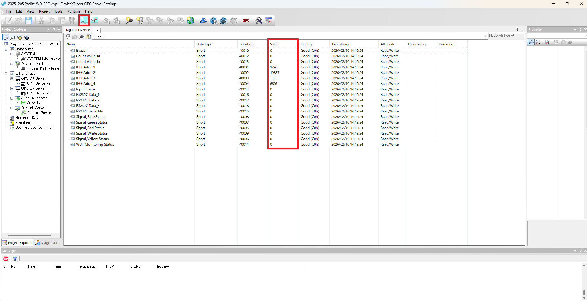
(5)You can monitor WDT data in real time using the ‘Tag Monitor’ function of DeviceXPlorer OPC Server.
This completes the connection setup between AirGRID and DeviceXPlorer OPC Server.
Connecting AirGRID with DeviceGateway
1. AirGRID Settings
Before starting, make sure to complete the required setup to receive data from the Patlite signal tower and the WDT (transmitter) through the WDR-PRO (receiver). Please refer to here.
2. DeviceGateway Settings
Configure the settings required to connect to AirGRID using Modbus Ethernet communication in DeviceGateway.
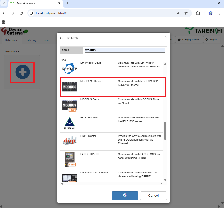
(1)In the DeviceGateway web configuration screen, open the [Data Source] tab and click the ‘+’ icon to open the new creation window. From the list of available devices, select [Modbus Ethernet], enter a name for the configuration, and click [OK].
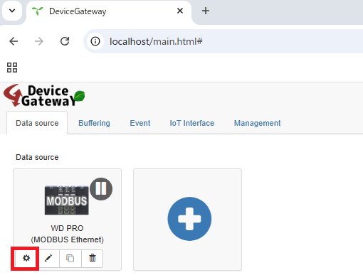
(2) Click the gear icon to open the data source settings screen.
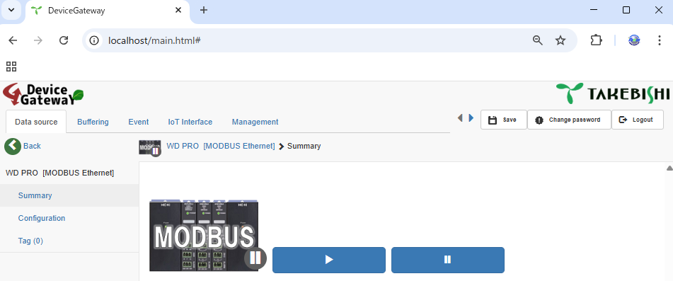
(3) On the Summary page, you can check the device’s connection, disconnection, and connection status.
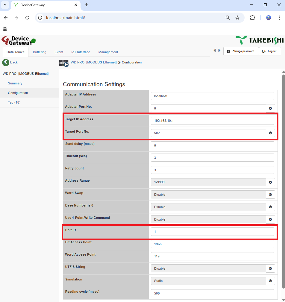
(4) On the “Communication Settings” page, enter the IP address configured for the WDR-PRO in “Device Address”, and set “Device Port Number” to 502 (default). Also, enter “1” in the “Unit ID” field.
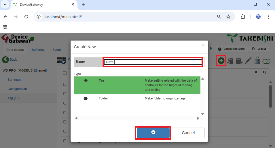
(5) Finally, on the “Tag” page, configure the access area settings. Click the “+” icon to open the new creation window. From the list of types, select Tag, enter a desired name, and click the (check mark) icon to save.
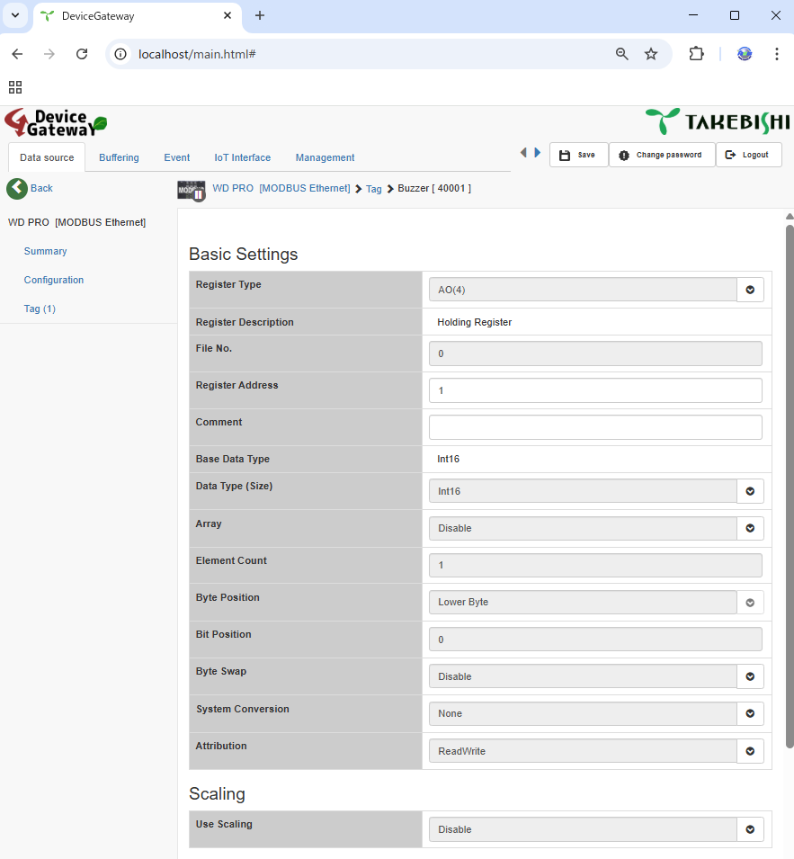
(6) Click the tag you created to configure its settings. AirGRID assigns WDT data to holding registers (addresses starting with ‘4’). For the list of data mappings, refer to the application note for the WDT.
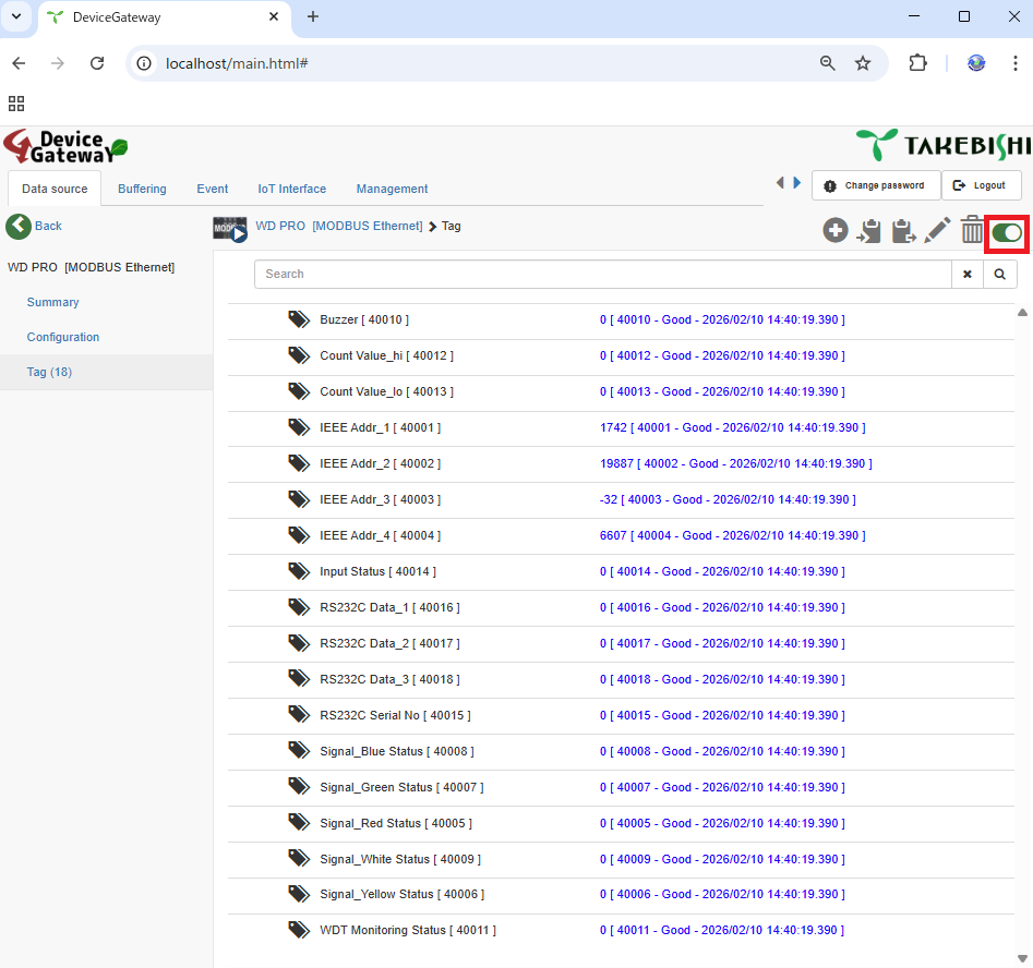
(7) When you turn [Monitor Function] ON in the upper-right corner of the screen, you can monitor WDT data in real time.
This completes the connection setup between AirGRID and DeviceGateway.
Products and Services Used
TAKEBISHI: DeviceXPlorer OPC Server DeviceGateway
Patlite: Wireless Data Collection System AirGRID WD (external link)